 Tue, Jan 16, 2007 |
 Tue, Jan 2, 2007 |
 Sun, Feb 11, 2007 |
 Sun, Feb 11, 2007 |
 Sun, Feb 11, 2007 |
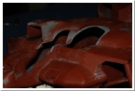
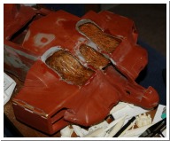
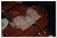
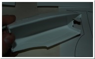
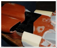
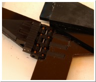
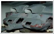
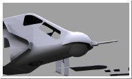
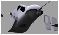
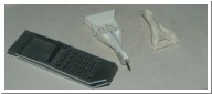
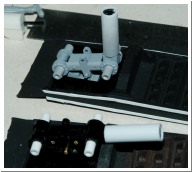
| telescoping brass struts for the APC ramp | accurately scaled chequerplate for the APC ramp. | I tried numerous times to get a decent front intake shape but I could never seem to get the overall shape right. | Solution - chop the existing intakes off completely | GRP to fill the holes |
 Sun, Feb 11, 2007 |
 Sun, Feb 11, 2007 |
 Sun, Feb 11, 2007 |
 Sun, Feb 11, 2007 |
 Sun, Feb 11, 2007 |
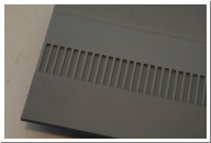
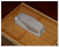
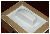
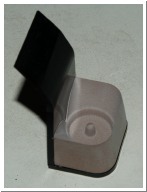
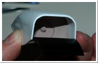
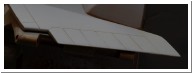
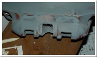
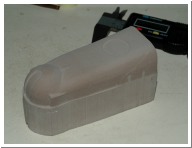
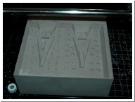
| bondo to get the shape back | Machined vacform buck. A paper template is stuck to it to make a guideline for cutting. My el-cheapo vacform table is made from an mdf box and since I couldn't be bothered drilling a bazillion holes I used predrilled electronic prototyping board. | Works fine. 2mm styrene over 48mm deep form. | Note the outline of the paper that was stuck to the buck. This provides an accurate line to trim the plastic. | checking the fit |
 Sun, Feb 11, 2007 |
 Sun, Feb 11, 2007 |
 Sun, Feb 11, 2007 |
 Sun, Feb 11, 2007 |
 Sun, Mar 4, 2007 |
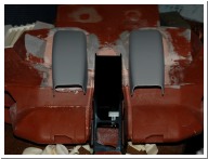
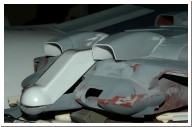
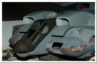
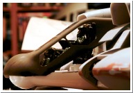
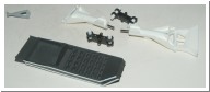
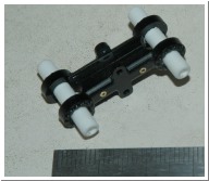
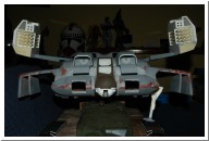
| Voila! | Also completely rebuilt the pod arms. They have intergral hinges and lock open at exactly 15 degrees. They're 3mm thinner than the ones provided and are mounted to a 3mm acrylic sheet which forms the roof of the APC bay. | I went through 3 iterations on the hinges. | Ended up with this wacky double joint to keep the centerline of the arms in a sensible place. The joints are made from layers of 3mm acrylic. | got bored and made a detail piece for inside the front intakes |
 Sun, Mar 4, 2007 |
 Sun, Mar 11, 2007 |
 Sat, Apr 7, 2007 |
 Mon, Apr 9, 2007 |
 Sun, Apr 15, 2007 |
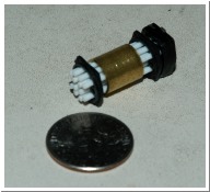
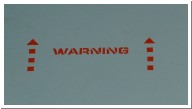
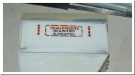
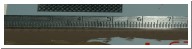
| It'll also help reinforce the vacformed intake | I'm getting too old for this teeny-tiny stuff... | seeing if it's possible to cut 3mm high text on a vinyl cutter. This looks a bit sloppy due to brush painted acrylic. Should airbrush fine though | looks like computer cut stencils should work - pain in the ass to make though | Rivets!!! Proof of concept. Hard to photograph. Polyester resin applied through computer cut vinyl stencil. 0.8mm diameter 0.08mm high |
 Mon, Apr 16, 2007 |
 Sun, Apr 22, 2007 |
 Sun, Apr 22, 2007 |
 Wed, Apr 25, 2007 |
 |
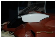
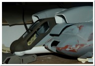
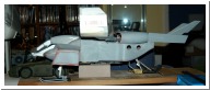
| more rivets | More major fuselage surgery. Lopped off the nose. The more I looked at pics of the 1:12 mini and the 1:1 the more I didn't like the shape of the halcyon nose. Also wanted to match the curvature of the window frames so... | Nose integrates into vacformed canopy. This will be vacformed in clear plastic then masked and painted for the window frames. Note also: rivets started on fuselage and port intake. | Testing masking for windows. Looks like it'll work. | I feel the need to replace the cockpit bottom as well. |
 |
 Sun, May 6, 2007 |
 Sun, May 6, 2007 |
 Sun, May 6, 2007 |
 |
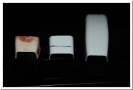
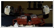
| checking the size of the gattling gun WRT the bottom hemisphere. | There'll be nothing left by the time I finish chopping bits off... | vacform buck for bottom of nose. | lining up to the top and bottom - they'll sit a bit closer together than this when I finish trimming the bottom. | checking the scale of rear skid strut. Used a 1/72 scale Avro Vulcan kit for reference. Also discovered they used the bulkhead between the engine bay and rear wheel bay of a Harrier for the "flap" at the back. |
 Sun, May 13, 2007 |
 Sun, May 13, 2007 |
 Sat, May 19, 2007 |
 Sun, May 20, 2007 |
 Sun, May 20, 2007 |
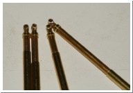
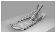
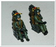
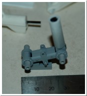
| resin Martin Baker seats - and temporary pilot figures. The seat is a close enough match for the pilots seat. The headrest will need some mods for the rear seat. | checking the seat positions | Front gear struts and skid. Top section of struts is reinforced with carbon fibre rod. Bottom section will be fabricated from brass tube. | More progress on the front gear. The axles from the vulcan gear are a prominent feature on the DS. These were machined from layers of 3mm acrylic. | Vulcan rear axle. One end is the pivot for the struts, the other end has to (somehow) securely attach to the skid. |
 Sun, May 20, 2007 |
 Sun, May 20, 2007 |
 Tue, May 22, 2007 |
 Tue, May 29, 2007 |
 Tue, May 29, 2007 |
| front strut mount and lower pivot | Hopefully an acrylic hinge will be strong enough to support the weight... | Master for the rear strut. Since it sits at a 30 degree angle off vertical when the gear is down I'll be casting it in white metal to prevent it bending under the weight. | A quick check of the overall geometry. | Working out how far off the ground it needs to be before fabricating the landing gear mounts. The full size and 1/12th scale had more ground clearance at the front than the rear (the aoshima rear gear is way to tall) |