 Sat, Jun 2, 2007 |
 Tue, Jun 5, 2007 |
 Tue, Jun 5, 2007 |
 Sat, Jun 9, 2007 |
 Sun, Jun 10, 2007 |
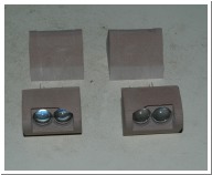
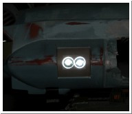
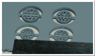
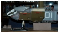
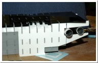
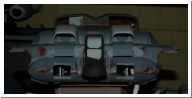
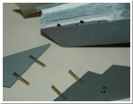
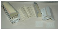
| Housing for the headlamps - 10mm white leds. The clear covers will be heat formed. | quick wiring check. | There's a small detail piece on the port side with the same configuration of holes as the minigun on the nose. It's a bit smaller though so I made 4 of different sizes to see which one looks correct. | Printed out some markings on paper to check the size. The 01 is a bit big everything else seems ok. | more fuselage surgery... cut out the front landing gear wells. |
 Sun, Jun 10, 2007 |
 Sun, Jun 17, 2007 |
 Mon, Jun 18, 2007 |
 Wed, Jun 20, 2007 |
 Wed, Jun 20, 2007 |
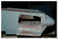
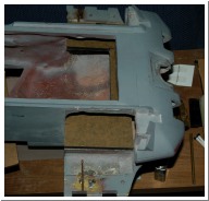
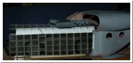
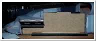
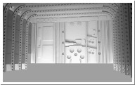
| 6mm acrylic horizontal bulkhead added as a base for rebuilding the front gear wells. | Starting on the cargo bay interior. BTW this won't fit anyone else's DS (unless you have a bandsaw). Also I didn't paint the APC - it'll be getting a coat of BB soon. | The only way this is going to fit is to completely replace the middle section of the DS. I'm not sure how feasable that will be without compromising the structural integrity. | See what I mean... | I'm going to mock-up the fuselage shell and support structure in 3mm acrylic - then see if I can make it from aluminium. |
 Sat, Jun 23, 2007 |
 Sat, Jun 23, 2007 |
 Sat, Jun 23, 2007 |
 Mon, Jun 25, 2007 |
 Mon, Jun 25, 2007 |
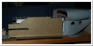
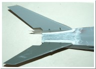
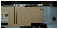
| this is all that's left of the original front | cargo bay outer wall template locks into horizontal bulkhead | cargo bay structure locks into 2 20mm aluminium tubes supporting the tail section | like this: | |
 Mon, Jun 25, 2007 |
 |
 Sat, Jun 30, 2007 |
 Sat, Jun 30, 2007 |
 Sat, Jun 30, 2007 |
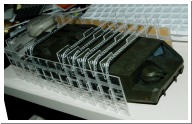
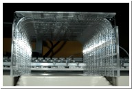
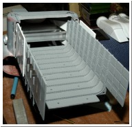
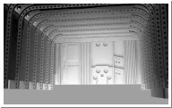
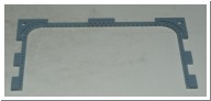
| Aluminium tubes supporting tail section also give somewhere for the VTOL ducts to hang. | roughing out the cargo bay rear panel in 3D | this may not look significant - but it's the first time since I chopped it in half that I've been sure I can get it back together. It's rigid and self supporting (without any glue yet) | The ribs are actually structural components since they interlock into the walls and roof. It's much more sturdy that I thought it would be. | BTW - this is what the ribs look like. Note tabs for locking into walls and ceiling and guide for the curved panels in the top corners |
 |
 Fri, Jul 6, 2007 |
 Mon, Jul 9, 2007 |
 Mon, Jul 9, 2007 |
 Mon, Jul 9, 2007 |
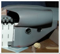
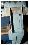
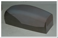
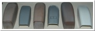
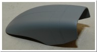
| more detailing on the rear wall - I wonder if I can mill the whole thing in one piece from 6mm acrylic. I need to figure out how to simulate 2 fluorescent tubes on each side | rear wall. Cleaning up the 9mm thick resin from the rear fuselage is going to be interesting... | Still not happy with the intake shape - the vacformed plastic ends up thinner on the sides than on the top so I made a wider buck to compensate. | v1, v2 and v3 intakes... | Wider intakes. Now I need to make new intake ramps... |
 Fri, Jul 13, 2007 |
 Thu, Jul 19, 2007 |
 Thu, Jul 19, 2007 |
 Thu, Jul 19, 2007 |
 Sun, Jul 22, 2007 |
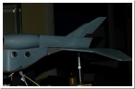
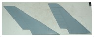
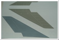
| scribed panel lines and rivets added. | somehow this doesn't look right. Vertical tailfins should sweep back more. Also the fuselage needs about 10mm added to the rear. So... | ...new tailfin. Original on right. The 1/12th scale mini only had 2 panel lines in the fins - the rest of the detail is all rivets. | rebuilt fin and computer cut rivet line template. I discovered locktite 5 minute epoxy is perfect for the rivets. | bulking up the tailfin roots with miliput |
 Sun, Jul 22, 2007 |
 Thu, Jul 26, 2007 |
 Thu, Jul 26, 2007 |
 Sun, Jul 29, 2007 |
 Sun, Jul 29, 2007 |
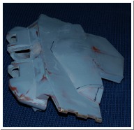
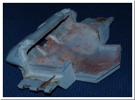
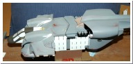
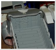
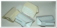
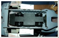
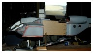
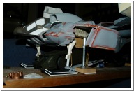
| brass tube epoxied in to support the tailfin joints | more reject parts... | Rear pods v4. Old ones were 4mm too high and didn't have enough space when stowed for the rear skids to fold up into. | APC is a tight squeeze. There's not enough room to detail the passenger seats behind the cockpit - or even get all the hanger bay roof to fit. | I'm not sure it's possible to enclose the front ramp struts in the cargo bay walls so they might end up "just for show" when the ramp is down. Note brass tubes epoxied in to the rear fuselage to reinforce the joint. |
 Sun, Jul 29, 2007 |
 Sun, Jul 29, 2007 |
 Sun, Jul 29, 2007 |
 |
 Fri, Aug 31, 2007 |
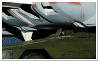
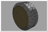
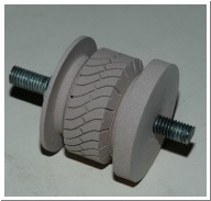
| ground clearance test | I made some adjustable "jacks" from threaded rod and tube so I can get the height right before locking the position of the landing gear. | about 2mm clearance for the "camera" on the top of the APC. | OK, so it's not DS related... but I'm going to make some replacement APC wheels with the correct tread pattern as a test for a 4th axis attachment to my CNC mill. | Like this... |