 Sun, Aug 26, 2007 |
 Sun, Aug 26, 2007 |
 |
 Tue, Aug 28, 2007 |
 Sun, Sep 2, 2007 |
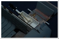
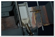
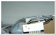
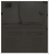
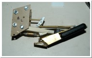
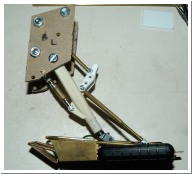
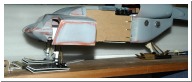
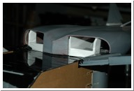
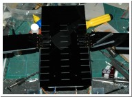
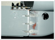
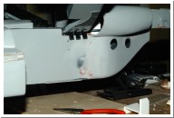
| rebuilding the front gear wells - and figuring out where to hang the struts | drawing up some detail for the landing gear wells | Landing gear wells. Brass tube inserted to reinforce the strut pivots. | landing gear in stowed position | |
 Sun, Sep 2, 2007 |
 Wed, Sep 5, 2007 |
 Wed, Sep 5, 2007 |
 Sun, Sep 9, 2007 |
 Sun, Sep 9, 2007 |
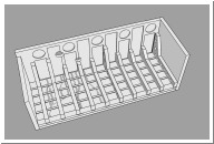
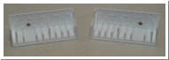
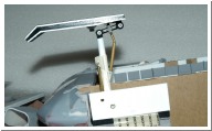
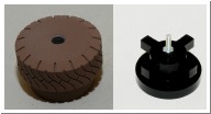
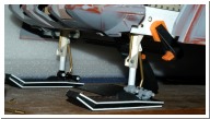
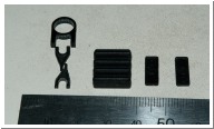
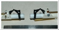
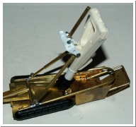
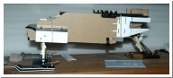
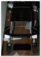
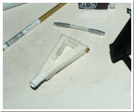
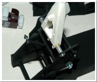
| landing gear deployed | APC tyre master and acrylic hub. Hub will be inserted into mould while tyre is cast in flexible black urethane. The flexible urethane is temperamental so I need to wait for warmer/dryer weather (it's winter down here) | Testing the stability of the front struts. | Some small parts for the front gear. | Added torque links to front struts |
 Sun, Sep 23, 2007 |
 Sun, Sep 23, 2007 |
 Sun, Oct 7, 2007 |
 Sun, Oct 7, 2007 |
 Sun, Oct 7, 2007 |
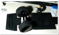
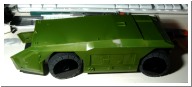
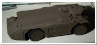
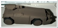
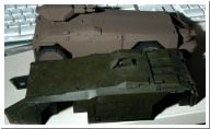
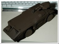
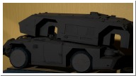
| urethane rubber tyres and steerable front axle | make that 4 wheel steering. Also found an unopened APC kit. After 20 years the plastic was a bit warped and very brittle. Assembling the top and sides took some creative clamping. | APC progress. First coat of paint (Humbrol 170) | Compared to the POS I was going to use.... | |
 Sun, Oct 14, 2007 |
 Thu, Oct 18, 2007 |
 Thu, Oct 18, 2007 |
 Thu, Oct 25, 2007 |
 Sun, Oct 28, 2007 |
| I'm calling this done for now. A coat of testors dullcoat and some very subtle black pastel weathering. I haven't permanently attached the body to the chassis yet so I can add some lighting. | matching Humbrol 170 with Tamiya acrylics. Humbrol on top, Tamiya mix on bottom. | Tamiya on top, humbrol on bottom. | Made a slightly bigger rear strut. I still need to find a clever way to lock it on this angle. | rear gear sub-assembly. Stowed position. |
 Sun, Oct 28, 2007 |
 Sun, Nov 4, 2007 |
 Tue, Nov 6, 2007 |
 Tue, Nov 6, 2007 |
 Sun, Nov 11, 2007 |
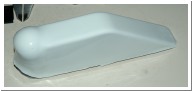
| rear gear sub-assembly. Deployed position. | A small milestone... the only thing holding it up is the landing gear. Rear end will sit a little higher than this when everything is permanently attached. | A peek inside at the internal structure. At the moment it sort of clips together. Should be rock solid when it's all glued. | The cargo bay box section needs to support the whole thing. | Vacform master for the canopy. There's a layer of styrene over it to provide a smooth surface for the clear canopy to be vacformed over. |
 Sun, Nov 11, 2007 |
 Mon, Nov 12, 2007 |
 Mon, Nov 12, 2007 |
 Sat, Nov 17, 2007 |
 Sun, Dec 9, 2007 |
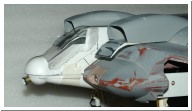
| The windows will be masked, then it'll be painted cockpit green (so it's green on the inside), then Brown Bess over the top. | vacformed clear headlamp covers | headlamp assembly | Figuring out the rear intakes based on the PH pic. | rear gear subframe |
 Sun, Dec 16, 2007 |
 Thu, Jan 3, 2008 |
 Thu, Jan 3, 2008 |
 Fri, Jan 4, 2008 |
 Fri, Jan 4, 2008 |
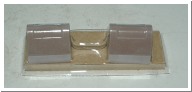
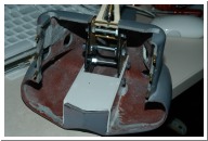
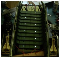
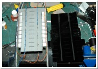
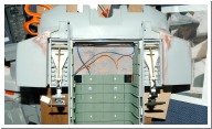
| cargo bay roof lights. | cargo bay lighting wiring.The LED leads are soldered together into 4 banks of 3 LEDs. The wiring and LED leads fit into channels milled into the top surface. Also note the tabs on the ribs which lock into slots in the top. | Pod arm hinges are also integral with the top surface. Once the top is glued to the cargobay there's no chance of getting at the wiring. | Wasn't happy with "permanently" attaching the rear strut to the subframe. Once the rear fuselage and cargo bay are joined there's no chance of getting at the rear subframe. So made a spring loaded pin axle. | Spring loaded axle means the rear gear can be attached after the rear fuselage, carbgobay and rear gear mount are permanently joined. |
 Fri, Jan 4, 2008 |
 Sun, Jan 6, 2008 |
 Sun, Jan 6, 2008 |
 Sun, Jan 6, 2008 |
 Sun, Jan 6, 2008 |
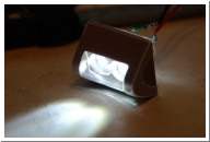
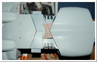
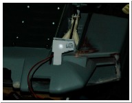
| Fuselage/tail joint. Fiberglass cloth and brass pins to reinforce the join. I need to be 100% sure I'm happy with the alignment before applying epoxy. | There's no going back now. Side walls epoxied and fiberglassed to the tail. One more coat of primer and it should be seamless. | Making sure the front end still lines up. | Because of the thickness of the resin I had to remove part of the cargo bar roof. I'll have to reattach it slightly lower. Also note the sidewalls interlock with the front fuselage section. | prototype front gear cover. 3mm LED ground down as far as it'll go provides a reasonable low profile lightsource. Hinges are nylon du-bro RC plane hinges. I'll probably make the final covers from sheet brass. |